Manless Aerial Device
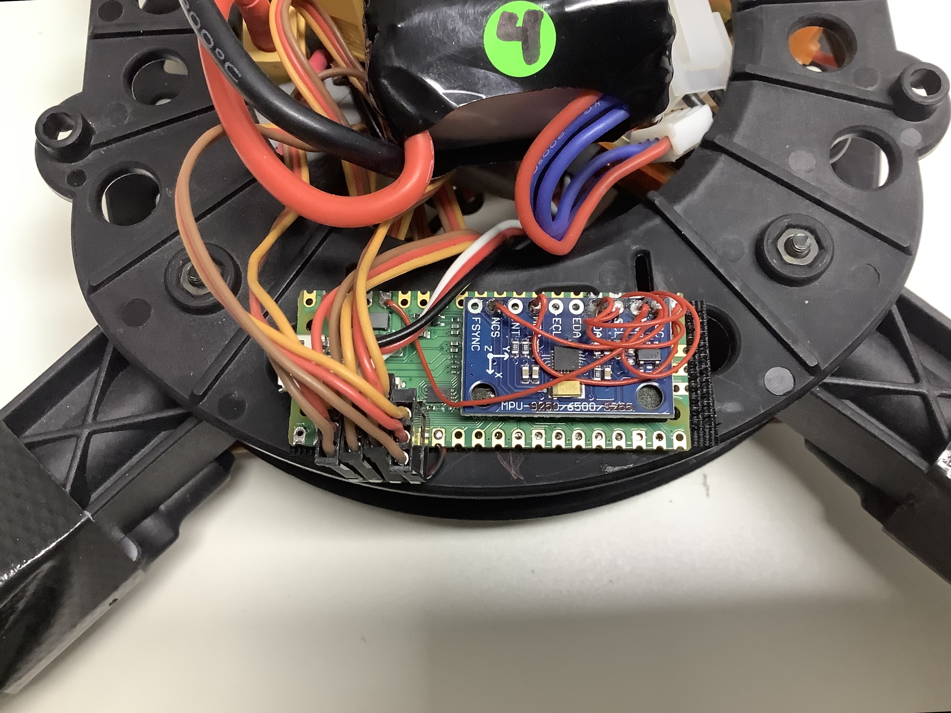
This is an Arduino library to build ESP32 / ESP32-S3 / RP2040 / STM32 flight controllers. A functional DIY flight controller can be build for under $10 from readily available development boards and sensor breakout boards. Ideal if you want to try out new flight control concepts, without first having to setup a build environment and without having to read through thousands lines of code to find the spot where you want to change something.
Installation: search for 'madflight' in the Arduino Library Manager, or download madflight from Github.
Quadcopter.ino is a 1000 line demo program for a quadcopter. It has been flight tested on ESP32, ESP32-S3, RP2040, and STM32F405 microcontrollers with the Arduino IDE. The program can be easily adapted to control your plane or VTOL craft. The source code has extensive documentation explaning what the settings and functions do.
Feedback is Welcome
I enjoy hacking with electronics and I'm attempting to write some decent code for this project. If you enjoy it as well, please leave some feedback in the form of Stars, Issues, Pull Requests, or Discussions. Thanks!
Required Hardware
- Development board:
- RP2040 (e.g. Raspberry Pi Pico)
- or ESP32 (e.g. Espressiv ESP32 DevKitC)
- or ESP32-S3 (e.g. Espressiv ESP32-S3 DevKitC)
- or STM32 (e.g. Black Pill or a commercial flight controller)
- SPI IMU sensor (BMI270, MPU9250, MP6500, or MPU6000), if not available then use an I2C IMU sensor (MPU6050 or MPU9150)
- RC Receiver: ELRS, CRSF, SBUS, DMSX, or PPM
- BEC or DC-DC converter to power your board from a battery
- ESC (OneShot125 or 50-490Hz PWM) and/or servos (50-490Hz PWM)
Optional Hardware
- GPS Module (Serial)
- Barometer (I2C BMP280, MS5611)
- Magnetometer (I2C QMC5883L)
- Current/Voltage Sensor (ADC or I2C INA226)
- Optical Flow Sensor (I2C)
Getting Started
- Install the Arduino madflight library
- Open example Quadcopter.ino in the Arduino IDE.
- Setup the USER-SPECIFIED DEFINES section
- If you're not using a default pinout (see below) then setup your board pinout in the BOARD section.
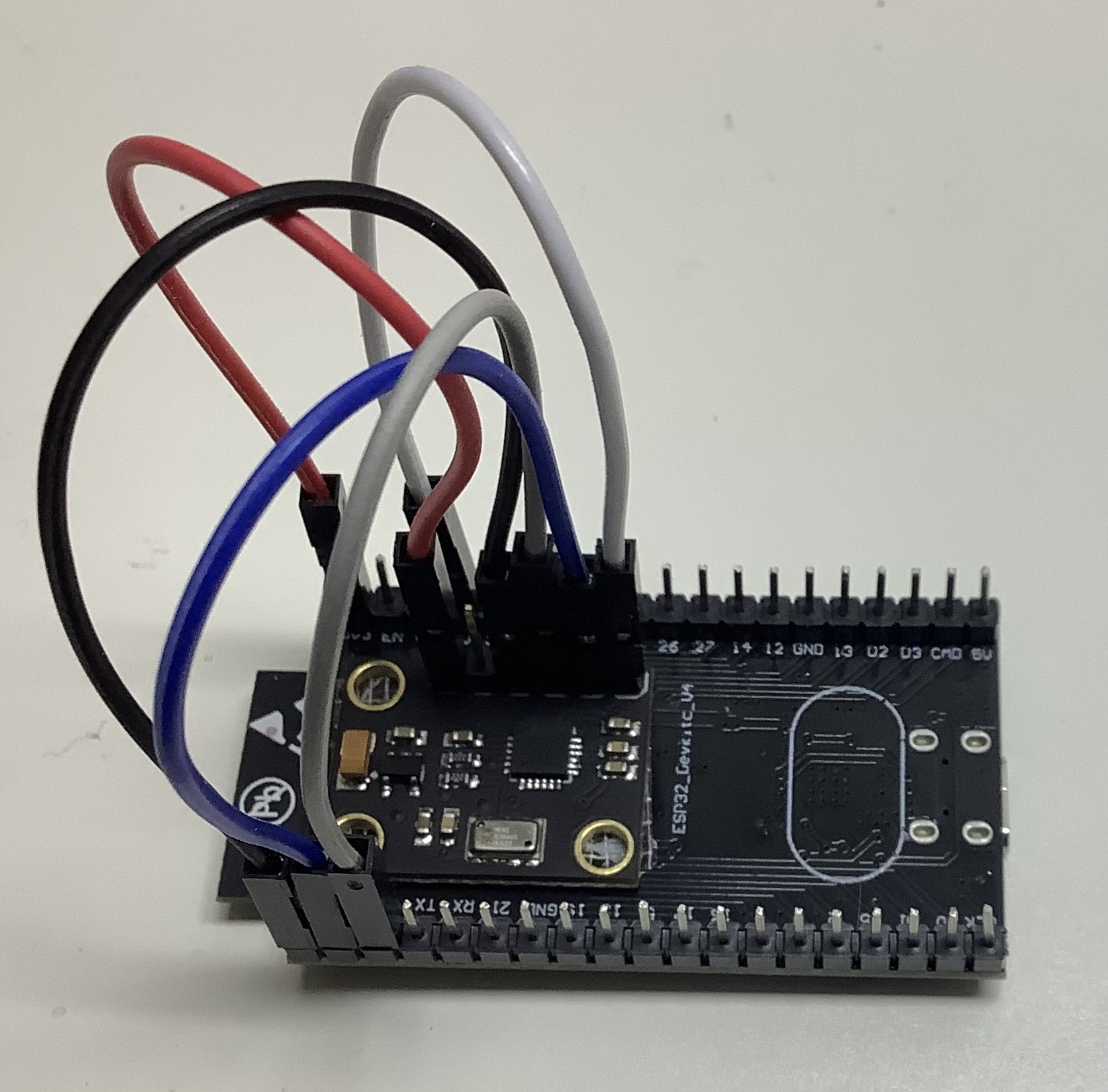
- Connect your IMU (gyro/acceleration) sensor as shown below.
- Compile and upload Quadcopter.ino to your board. Connect the Serial Monitor at 115200 baud and check the messages. Type
helpto see the available CLI commands. - Use CLI print commands like
pimu,pgyro,prollto Check that IMU sensor and AHRS are working correctly. - IMPORTANT: Use CLI
calimuandcalmagto calibate the sensors. - Connect radio receiver to your development board according to the configured pins.
- Edit the RC RECEIVER CONFIG section. Either match you RC equipment to the settings, or change the settings to match your RC equipment.
- Check your radio setup: Use CLI
ppwmandpradioto show pwm and scaled radio values. - Connect motors (no props) and battery and check that motor outputs are working correctly. For debugging, use CLI
pmotto show motor output. - Mount props, go to an wide open space, and FLY!FLY!
Safety First!!!
By default madflight has these safety features enabled:
- Motors only rotate when armed.
- Arming Procedure: set throttle low then flip the arm switch from disarmed to armed.
- Kill Switch: when the arm switch is in the disarm position, disarm and stop motors until re-armed.
- Failsafe: when radio connection is lost, disarm and stop motors until re-armed.
- Armed Low Throttle: motors run at low speed, to give visible armed indication.
- LED armed/disarmed indicator.
Software Design
- Keep it simple!!!
- Based on dRehmFlight
- Coded primarily for readability, then for speed and code size.
- No external dependencies, all modules are included in the
src/madflightdirectory. - The madflight flight controller runs standard
setup()andloop(). - It mainly uses plain Arduino functionality: Serial, Wire, and SPI. One custom hardware dependent library is used for PWM. Therefor, it can fairly easily ported to other 32 bit microcontrollers that support the Arduino framework. Also porting to other build environments like PlatformIO or CMake should not be a huge effort.
- The following modules are used:
imuInertial Measurement Unit, retrieves accelerometer, gyroscope, and magnetometer sensor dataahrsAttitude Heading Reference System, estimates roll, yaw, pitchrcinRC INput, retrieves RC receiver datacontrolPID controller and output mixeroutOutput to motors and servosmagMagnetometer (external)baroBarometergpsGPS receiverbbBlack Box data loggercliCommand Line Interface for debugging, configuration and calibrationcfgRead and save configuration to flashhwHardware specific code for STM32, RP2040 and ESP32
- Most modules are interfaced through a global object, for example the
imuobject has propertyimu.gxwhich is the current gyro x-axis rate in degrees per second for the selected IMU chip. - For a quick overview of the objects, see header
src/madflight/interfaces.hwhich defines the module interfaces. - The module implementations are in subdirectories of the
src/madflightdirectory. Here you find the module header file, e.g.src/madflight/imu/imu.h. In theextrasdirectory your find test programs for the modules, e.g.extras/TestMadflight/imu.ino. - The module files are usually header only, that is, the header also includes the implemention.
Connecting the IMU Sensor
SPI sensor: (highly recommended over I2C)
  Sensor       Dev Board
SCL/SCLK <---> SPI_SCLK
 SDA/SDI <---> SPI_MOSI
 ADD/SDO <---> SPI_MISO
     NCS <---> IMU_CS
     INT <---> IMU_EXTI
     VCC <---> 3V3
     GND <---> GND
I2C sensor:
  Sensor       Dev Board
     SCL <---> I2C_SCL
     SDA <---> I2C_SDA
     INT <---> IMU_EXTI
     VCC <---> 3V3
     GND <---> GND
Pinout ESP32
Default pinout for ESP32, using the Espressiv ESP32 DevKitC (38 pin) board. This pinout is defined in madflight_board_default_ESP32.h, but can be modified with #define HW_PIN_XXX in your program.
| Function | GPIO | Board | GPIO | Function |
|---|---|---|---|---|
| 3V3 out | 3V3 | Antenna side | GND | GND |
| reset button | EN | 23 | I2C_SDA | |
| SPI_MISO | VP 36 input only | 22 | I2C_SCL | |
| IMU_EXTI | VN 39 input only | 1 TX | USB Serial Debug TX | |
| BAT_V | 34 input only | 3 RX | USB Serial Debug RX | |
| RCIN_RX | 35 input only | 21 | SPI_MOSI | |
| RCIN_TX | 32 | GND | GND | |
| PWM1 | 33 | 19 | SPI_SCLK | |
| PWM2 | 25 | 18 | IMU_CS | |
| PWM3 | 26 | strap 5 | GPS_TX | |
| PWM4 | 27 | 17 | GPS_RX | |
| PWM5 | 14 | 16 | PWM11 | |
| PWM6 | 12 | 4 | PWM10 | |
| GND | GND | boot 0 | PWM9 | |
| PWM7 | 13 | strap 2 | LED | |
| nc | D2 9 flash | strap 15 | PWM8 | |
| nc | D3 10 flash | flash 8 D1 | nc | |
| nc | CMD 11 flash | flash 7 D0 | nc | |
| 5V input (*) | 5V | USB connector | flash 6 CLK | nc |
Note: During boot the input voltage levels (pull up/pull down) on strap pins have a configuration function, therefor these pins are used as output only.
(*) 5V input via diode from BEC. Without a diode take care not connect USB and the battery at the same time!
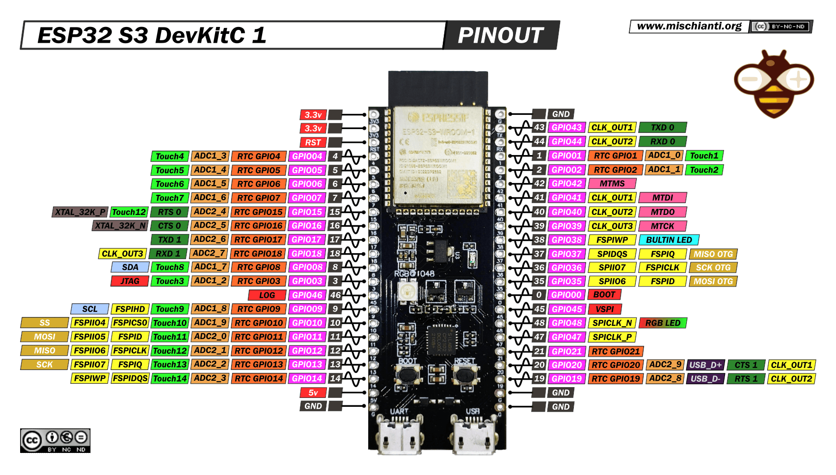
Pinout ESP32-S3
Default pinout for ESP32-S3, using the Espressiv ESP32-S3 DevKitC-1 (44 pin) board. This pinout is defined in madflight_board_default_ESP32-S3.h, but can be modified with #define HW_PIN_XXX in your program.
| Function | GPIO | Board | GPIO | Function |
|---|---|---|---|---|
| 3V3 out | 3V3 | Antenna side | G | GND |
| 3V3 out | 3V3 | 43 | TX serial debug UART port | |
| reset button | RST | 44 | RX serial debug UART port | |
| PWM1 | 4 | 1 | - | |
| PWM2 | 5 | 2 | - | |
| PWM3 | 6 | 42 | - | |
| PWM4 | 7 | 41 | - | |
| PWM5 | 15 | 40 | - | |
| PWM6 | 16 | 39 | - | |
| RCIN_TX | 17 | 38 | LED | |
| RCIN_RX | 18 | 37 | - | |
| I2C_SDA | 8 | 36 | - | |
| GPS_RX | 3 | 35 | - | |
| GPS_TX | 46 | 0 | boot button | |
| I2C_SCL | 9 | 45 | - | |
| IMU_CS | 10 | 48 | RGB_LED | |
| SPI_MOSI | 11 | 47 | - | |
| MISO | 12 | 21 | - | |
| SCLK | 13 | 20 | USB_D+ (serial debug alternate) | |
| IMU_EXTI | 14 | 19 | USB_D- (serial debug alternate) | |
| 5V in (*) | 5V | G | GND | |
| GND | G | USB connector | G | GND |
(*) 5V input via diode from BEC. Without a diode take care not connect USB and the battery at the same time!
Pinout RP2040
Default pinout for RP2040, using the Raspberry Pi Pico (40 pin) board. This pinout is defined in madflight_board_default_RP2040.h, but can be modified with #define HW_PIN_XXX in your program.
| Function | GPIO | Board | GPIO | Function |
|---|---|---|---|---|
| RCIN_TX | 0 | USB connector | VBUS | nc |
| RCIN_RX | 1 | VSYS | 5V input via diode (*) | |
| GND | GND | GND | GND | |
| PWM1 | 2 | EN | nc | |
| PWM2 | 3 | 3.3V out | 3V3 | |
| PWM3 | 4 | VREF | nc | |
| PWM4 | 5 | 28_A2 | BAT_V | |
| GND | GND | GND | GND | |
| PWM5 | 6 | 27_A1 | - | |
| PWM6 | 7 | 26_A0 | - | |
| GPS_TX | 8 | RUN | reset button to GND | |
| GPS_RX | 9 | 22 | IMU_EXTI | |
| GND | GND | GND | GND | |
| PWM7 | 10 | 21 | I2C_SCL | |
| PWM8 | 11 | 20 | I2C_SDA | |
| PWM9 | 12 | 19 | SPI_MOSI | |
| PWM10 | 13 | 18 | SPI_SCLK | |
| GND | GND | GND | GND | |
| PWM11 | 14 | 17 | IMU_CS | |
| PWM12 | 15 | JTAG pins | 16 | SPI_MISO |
Consecutive even/odd PWM pins (e.g. pins 2,3 or 10,11) share the same timer and have the same frequency.
(*) 5V input via diode from BEC. Without a diode take care not connect USB and the battery at the same time!
Pinout STM32
Default pinout for STM32, using the WeAct STM32F411 Black Pill (40 pin) board. This pinout is defined in madflight_board_default_STM32.h, but can be modified with #define HW_PIN_XXX in your program.
| Function | GPIO | Board | GPIO | Function |
|---|---|---|---|---|
| nc | VB | SWD pins | 3V3 | 3V3 out |
| LED | C13 | G | GND | |
| - | C14 | 5V | 5V input (*) | |
| - | C15 | B9 | PWM10(t4) | |
| nc | R | B8 | PWM9(t4) | |
| - | A0 | B7 | I2C_SCL | |
| - | A1 | B6 | I2C_SDA | |
| GPS_TX | A2 | B5 | PWM8(t3) | |
| GPS_RX | A3 | B4 | PWM7(t3) | |
| IMU_CS | A4 | B3 | RCIN_RX | |
| SPI_SCLK | A5 | A15 | RCIN_TX | |
| SPI_MISO | A6 | A12 | USB_DP | |
| SPI_MOSI | A7 | A11 | USB_DN | |
| BAT_I | B0 | A10 | PWM6(t1) | |
| BAT_V | B1 | A9 | PWM5(t1) | |
| - | B2 | A8 | PWM4(t1) | |
| IMU_EXTI | B10 | B15 | PWM3(t1) | |
| 3V3 out | 3V3 | B14 | PWM2(t1) | |
| GND | G | B13 | PWM1(t1) | |
| 5V input (*) | 5V | USB connector | B12 | - |
Internally connected: C13 - LED, A0 - key button
PWM1-6 are connected to timer1, PWM7-8 to timer3 and PWM9-10 to timer4. PWM pins connected to the same timer operate at the same frequency.
(*) 5V input via diode from BEC. Without a diode take care not connect USB and the battery at the same time!
Pinout STM32 Of-the-shelf Flight Controllers
In the src directory you'll find header files for 400+ commercial flight controllers. These are converted Betaflight configuration files. Include the header file of your board, and in your program set '#define HW_USE_XXX' to match your board.
Changes from dRehmFlight
- Add support for RP2040, ESP32, ESP32-S3, and STM32
- Dropped Teensy support, but could be re-added by creating a hw_TEENSY.h file. (I just don't have the hardware to test on)
- Moved all hardware specific code to hw_XXX.h and added hardware specific libraries
- Reduced the number of global variables
- Oneshot is implemented as PWM up to 3.9kHz
- New libs for IMU sensors
- Changed arming logic
- Loop rate set to 1kHz to match IMU sensor rate
- Interrupt driven IMU operation by default, but setup/loop still possible
Flight Controllers on Github
In (approximate) increasing order of complexity.
| Flight Controller | Features | Development Environment | Microcontroller |
|---|---|---|---|
| drone-flight-controller | Single 700 line ino file, no libs | Arduino | ATmega328P |
| dRehmFlight | Quad, Plane, VTOL | Arduino | Arduino Teensy 4 |
| madflight | Quad, Plane, VTOL, based on dRehmFlight | Arduino | ESP32, RP2040, and STM32 |
| esp-fc | FPV Quad | PlatformIO | ESP32 |
| Crazyflie | FPV Quad | STM32F405 | |
| esp-drone | FPV Quad, forked from Crazyflie | ESP32 | |
| Betaflight | FPV Quad, based on cleanflight | STM32 F4/F7/H7 | |
| inav | Plane, based on cleanflight | STM32 F4/F7/H7 | |
| Ardupilot | Quad, Plane, VTOL | Linux waf | STM32 F4/F7/H7 or Linux based |
| PX4-Autopilot | Quad, Plane, VTOL | STM32 F4/F7/H7 |
Disclaimer
This code is a shared, open source flight controller for small micro aerial vehicles and is intended to be modified to suit your needs. It is NOT intended to be used on manned vehicles. I do not claim any responsibility for any damage or injury that may be inflicted as a result of the use of this code. Use and modify at your own risk. More specifically put:
THIS SOFTWARE IS PROVIDED BY THE CONTRIBUTORS "AS IS" AND ANY EXPRESS OR IMPLIED WARRANTIES, INCLUDING, BUT NOT LIMITED TO, THE IMPLIED WARRANTIES OF MERCHANTABILITY AND FITNESS FOR A PARTICULAR PURPOSE ARE DISCLAIMED. IN NO EVENT SHALL THE CONTRIBUTORS BE LIABLE FOR ANY DIRECT, INDIRECT, INCIDENTAL, SPECIAL, EXEMPLARY, OR CONSEQUENTIAL DAMAGES (INCLUDING, BUT NOT LIMITED TO, PROCUREMENT OF SUBSTITUTE GOODS OR SERVICES; LOSS OF USE, DATA, OR PROFITS; OR BUSINESS INTERRUPTION) HOWEVER CAUSED AND ON ANY THEORY OF LIABILITY, WHETHER IN CONTRACT, STRICT LIABILITY, OR TORT (INCLUDING NEGLIGENCE OR OTHERWISE) ARISING IN ANY WAY OUT OF THE USE OF THIS SOFTWARE, EVEN IF ADVISED OF THE POSSIBILITY OF SUCH DAMAGE.
Logo image copyright (c) 1975 Deutsches MAD Magazine. This project is not associated with MAD Magazine.


